
Building and Scaling a Micro-Segmented Network in AWS
Update 05/05/2020 – Considerations for dealing with situations where avoiding asymetric routing is a requirement
Life is full of competing priorities, and technology is certainly no exception. For some time we have known that the safest system is one that allows the minimal number of people or other systems access. For computer networks, this leads to a fairly obvious ideal configuration where each interface only allows pre-approved connections both inbound and outbound. Further, we would want to be able to inspect the traffic being sent to look for signs of intrusion or attack. Historically, the cost to achieve this desired state has been at odds with the perceived benefits, but with the advent of the cloud, we can get closer than ever before!
Internet Protocol Addressing and Routing
Where the rubber hits the road and the internet we all know and love becomes real is in the world of IP (“internet protocol”) and the two most common session protocols TCP (“transmission control protocol”) and UDP (“user datagram protocol”).
Let’s break down how data moves between network interfaces in a typical network, leaving out how the data gets generated by the application and picking up at the IP layer. IP provides the methodology for ensuring that chunks of data known as “packets” can be moved from one network interface to another across separately managed networks. The smallest logical “network” is the subnet. Within a subnet, network interfaces can generally communicate directly with each other. We generally use what are known as “switches” to hook up the various network interfaces that are part of the same subnet.
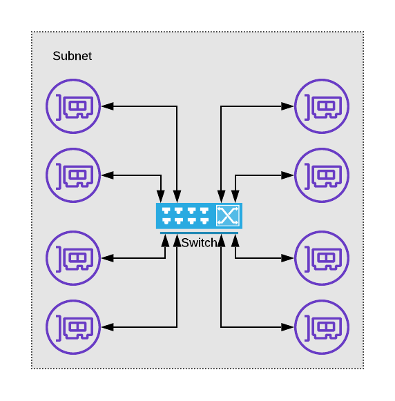
a depiction of how a switch and network interfaces relate
In IP, a subnet is generally described by it’s starting IP and the size of the subnet in the form of a bitmask length. For example, the network 10.0.0.0/8 starts at IP 10.0.0.0, and ends at 10.255.255.255. The “/8” portion indicates that you can identify this subnet by the first 8 bits of the address, and the remaining 24 bits are used to identify the interface within the network.
For a packet to move between subnets, we rely on devices that provide “routing” functionality. For an IP based network, these routers examine the destination IP address of a given packet, consult the “routing table” associated with the network interface the packet arrived from, and use the resulting destination interface to push the packet back out.
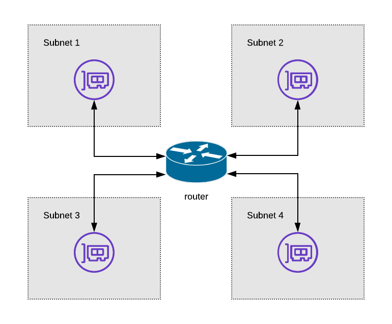
Router Diagram
What might the ideal rule controlling traffic between interfaces look like then? Perhaps we require the packet be proven to come from a known user, being sent to a known application, and whose contents can be guaranteed to not have been modified in transit? (spoiler alert — research “service mesh” to see how to get close to this!)
You may have noticed that the devices we’re discussing are getting more and more complex in their decision making — switches simply look at the physical address (the “MAC” address) of the packet’s destination and push it out the appropriate port, while routers must analyze the IP address and lookup routing rules. This increasing complexity is no accident, and is designed to balance the trade-off between the granularity of protection afforded in the network and the expense of the devices connecting those devices. Not to mention the complexity of managing all those rules!
What Virtualization has Bought Us
When devices were predominantly physical in nature we generally purchased switches, routers, firewalls, and other network devices that were also primarily physical. This lead to increased pressure to create “flat” networks in order to keep costs down, which resulted in large swaths of systems were on the same subnet able to communicate directly. Is it any surprise then that many application owners don’t fully understand and appreciate the various network connection dependencies their applications have?
With the advent of virtualization, and especially with concepts introduced by various cloud vendors such as the “Virtual Private Cloud (VPC)” and “Virtual Network (VNET)” we now have the tools necessary to right size our subnets and enforce more intelligent connection rules than ever.
Layered Security
Within AWS we have the concept of a “security group”. These are applied to the various network interfaces (called ENI or elastic network interface) and provide a mechanism to supply IP-level inbound and outbound rules. This means we can enforce rules such as “this network interface is allowed to accept connections from the 10.0.1.0/24 network” or “this interface is allowed to initiate connections to the 0.0.0.0/0 network” and meet one part of our ideal state network control goals. Good stuff!
Unfortunately, while this provides a degree of security and control, it does not inspect the packet contents to ensure they aren’t malicious. Further, in regulated environments, we need to ensure that changes to connectivity between applications are fully auditable to remain compliant. We can provide auditability via secure CI/CD pipelines and infrastructure as code, but in many environments, we have legacy processes or immature teams where a more traditional firewall-based control plane is required.
How in AWS might we achieve our goals of micro-segmented networks with such a firewall control plane injected?
Key AWS Building Blocks
Before we can design a solution, we should spend a few moments analyzing the components that are used to create networks within AWS.
Virtual Private Cloud (VPC)
Virtual Private Clouds are the AWS mechanism of defining a private network within the AWS cloud. VPCs are a concept built on top of the AWS hyperplane, and well worth a deep dive! For our conversation here, it is most relevant to keep the following in mind:
- VPCs are “flat” with respect to ENI to ENI communication. You cannot create a route out of the VPC for an IP address that lives within the IP address. You are expected to use security groups at this level.
- Creating a VPC is free
- VPCs are a region level construct within AWS
VPC Subnet
Within the VPC you define a series of subnets. These subnets must be within the set of IP CIDRs that have been associated with a VPC and are bound to a particular availability zone (AZ). Each subnet has a routing table that is used to determine the “next hop” based on the destination address.
VPC Route Table
The mechanism for determining these next hops is the VPC route table. Typical next hops used within a routing table within AWS are the following:
- Internet Gateway (IGW)
- NAT Gateway (NGW)
- Elastic Network Interface (ENI)
- Virtual Gateway (VGW)
- Transit Gateway (TGW)
- VPC Peer
- Gateway Interface Endpoint (for example to provide private access to S3 or DynamoDB)
Keep in mind that if the destination address is contained within the IP CIDRs associated with the VPC it is considered “local” and you will not be allowed to create a route for such an address.
VPN Connection
AWS VPN connections are established between a “Customer Gateway (GGW)” which specifies the IP addresses where the remote side (non-AWS) of the VPN tunnel should be connected and whether automated route table exchange should happen via BGP. This dynamic route exchange option requires you to select an autonomous system number (ASN). Keep this ASN in mind — we’ll need it shortly as we discuss the transit gateway.
Once the CGW has been created, you create the VPN by specifying the CGW and either a virtual private gateway or as we will use in this example, a transit gateway.
Internet Gateway
The internet gateway is required for your VPC to have a direct connection to the internet. You attach it to your VPC, then in a route table create an appropriate route. For example, you can create a “public” subnet by routing 0.0.0.0/0 to the IGW, and by either attaching an elastic IP to an ENI or allowing the ENI to acquire an automatic public address.
NAT Gateway
The most common way to provide outbound internet access for network interfaces within a VPC that you do not wish to be publicly addressable is by creating a NAT Gateway. You typically place the NAT gateway in a “public” subnet as described above, then set the 0.0.0.0/0 route of “private” subnets to be the NAT Gateway. While NAT Gateways are highly available, and autoscale to meet capacity demands, they do not provide any traffic inspection or filtering capabilities.
Transit Gateway (TGW)
The transit gateway exists to provide a solution for interconnecting many VPCs. While it is possible to create a “mesh” of peered VPCs to allow them to communicate, maintaining such an arrangement creates management overhead and as the number of VPCs in an enterprise increases you quickly reach the limits of peering connections.
Instead of requiring you to create such a mesh, the transit gateway functions more as a hub-and-spoke model. You attach a VPC to the transit gateway by specifying the subnets in which to place the TGW’s network interfaces, then update the route tables of the subnets that should be able to access the broader network to reference the transit gateway. If you specify this route as 0.0.0.0/0, you can force all non-local traffic to go through the transit gateway.
Each attachment of a VPC to the transit gateway is associated with a TGW route table. These route tables can be used to force all traffic between VPCs to run through a central “inspection” VPC which we will refer to as the “core.”
Equal Cost Multi-path Routing (ECMP)
The concept of equal-cost multi-path routing is that when multiple routes are advertised between two destinations and they have the same “cost” a network can choose to balance each stream across the available connections. As a result, we gain two key benefits — scale and availability.
For some time AWS has supported ECMP across Direct Connect, and with the introduction of the Transit Gateway, they added ECMP for VPN connections. We will take full advantage of this!
Custom Network Appliances in AWS
As discussed earlier when reviewing route tables, a potential target of a route within AWS is an Elastic Network Interface (ENI). This enables us to add custom devices (for example next-generation firewalls, or transparent proxies) and set routing up such that traffic must pass through these devices. Pretty cool, but now we must solve for both scaling and availability subject to all the typical AWS limitations.
What can we do to create a highly available solution? We can certainly minimize our mean time to recovery (MTTR) by setting up a warm spare, and upon a health check failing automatically update the route table to fail over to the spare device, and this is indeed a reasonable solution for availability — but does nothing to address how we can scale.
To scale in this arrangement, we would need to limit the devices pointing to a particular appliance by creating multiple subnets, each with a dedicated appliance, and individualized health monitoring and spare capacity.
Is there a better solution?
Marrying the Building Blocks and Creating a Highly Available, Scalable Network Core
Lets begin by describing a few key characteristics we’d like our approach to have:
- Meet service level agreements made to each network segment (“workload VPC”) in the form of guaranteed-available minimum bandwidth transiting the core.
- Ensure failure of an individual device affects at most a single network stream, where a reconnect of that stream will immediately be re-routed.
- Be easy to reason about in terms of the connectivity path, failure modes, approach to scaling, and how we would recover.
- Failure of each component results in a secure, and where ever possible, continuously available environment.
To get over the limitations of routing to an ENI, we can use the ECMP capabilities of the TGW to create a fleet of devices to perform the type of inspection and advanced rule evaluation we’re interested in doing. On the other side of that device, the native attachment mechanisms of the TGW are already highly available and scalable.
Ensuring we can meet our obligations to our workload VPCs that will be routed through the fleet is now a simple matter of adding up the required capacity, and dividing by the maximum capacity of an individual device. To reach an acceptable level of risk for our availability targets we can take this capacity based device count, and add a number of additional devices. Unlike our previous scenario where the extra devices were warm, but not adding capacity, in this scenario, they are actually hot — able to directly increase the overall capacity of the system while they enable us to meet our availability targets!
Both failure and updates to the fleet can be handled by either a rolling deployment, or by creating an entirely new core, and updating the TGW’s route table to point to the new ECMP balanced set of VPN connections!
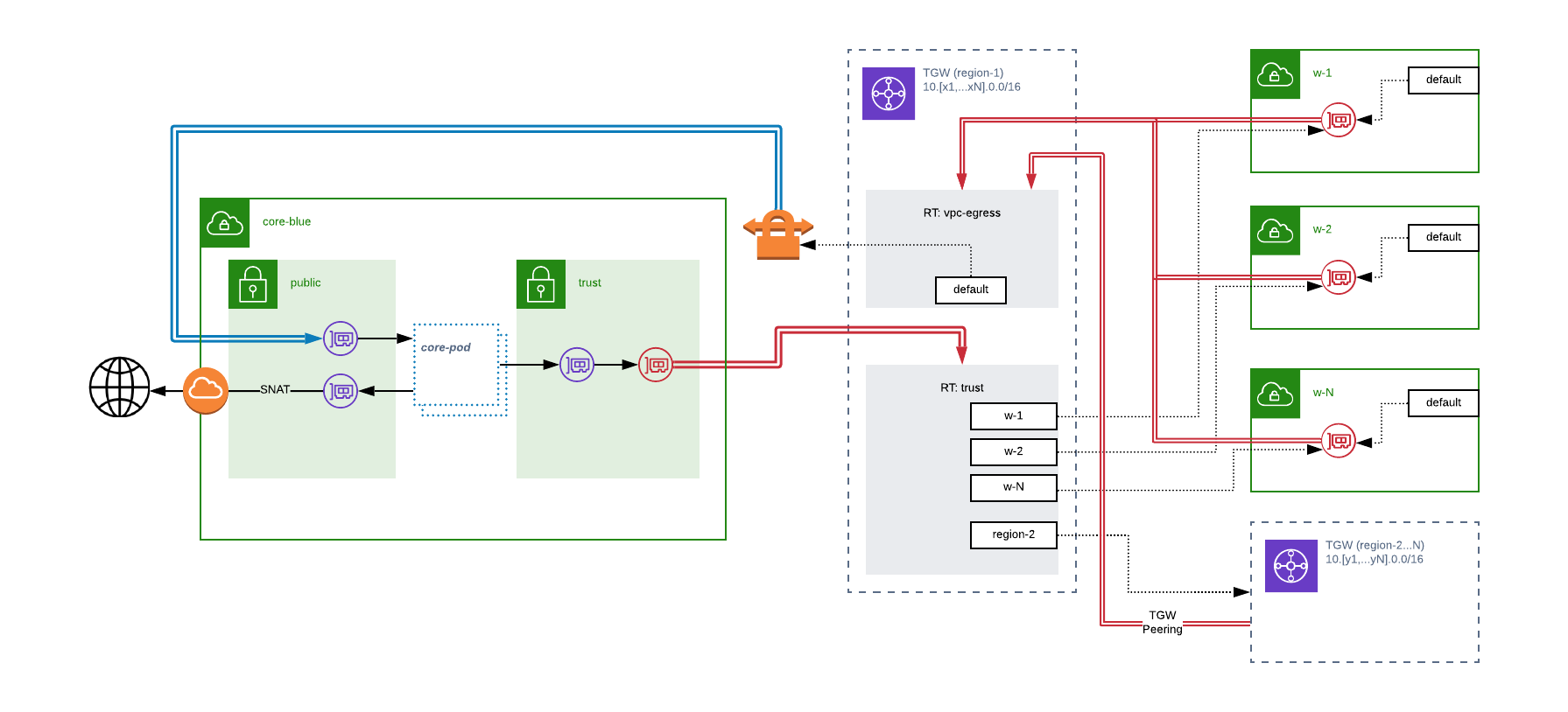
High Level Diagram
To ensure we don’t allow an individual workload to consume more than its fair share of the available capacity in the core, we can use simple quality of service controls on each device in the fleet. By taking the (promised capacity / # required devices) and setting that as the upper limit on any individual device, we ensure each workload network gets its fair share, while the extra “hot” devices enable the workloads access to additional capacity should they need it. By setting the limit on a stream-by-stream basis, we also encourage teams responsible for the workloads to use multi-threaded connection approaches. A win-win!
The Core “Pod”
In designing our scaling unit for our network core — the “pod” — we need to keep a few things in mind. To meet our objectives of the system being easy to support and be reasoned about, each component needs to perform a clearly defined and testable set of tasks. So what are the tasks implicit in our proposed configuration?
- VPN Termination — the TGW will be targeting our pod with a VPN connection, and these connections must share a AS number to enable ECMP
- Rate Limiting / QoS — each pod holds the responsibility of limiting traffic sources to the pre-agreed upon amount of capacity in order to ensure our core meets the provided SLAs
- Rule Evaluation — we must have a methodology of introducing a device capable of performing the deep inspection of data transiting our core
- Bootstrapping & Management— each component in the pod will have bootstrapping processes (license activation, software downloads, etc.). Further, management and/or diagnostic access should be supported.
- Observability — each of the tasks our pod is responsible for will have key performance indicators that should be captured and exposed for analysis.
So what goes into a pod?
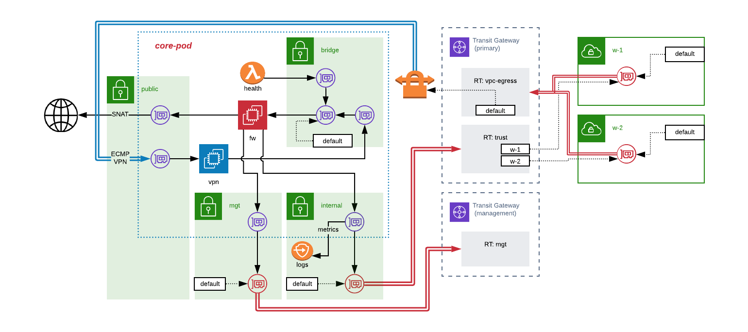
Detail Level Diagram
In this architecture, we split the computing tasks of a pod into two distinct instances — one to handle the VPN termination and QoS tasks, and one to act as our filtering device. You could, of course, create one device to perform all these tasks, but in many cases, it is desirable to use an “off the shelf” next-gen firewall device and keeping them separate means the configuration required can be considerably simpler.
To help break down the approach, let’s follow the path of a packet leaving one workload “w-1” and heading to another “w-2” or to the internet:
- W-1’s subnets have their default route set to send packets to transit gateway.
- Transit gateway evaluates w-1’s VPC attachment and determines the appropriate route table is the “vpc-egress” route table.
- The default route of the vpc-egress route table sends the packet out of the TGW via the ECMP VPN link.
- Packet is received by the “vpn” instance located in the pod.
- QoS rules are enforced by vpn instance before sending packet out via ENI located in the bridge subnet.
- Bridge subnet’s default route is the ENI of the “fw” instance, so packet is sent there.
- Fw instance evaluates its ruleset for the packet, assuming rules pass, packet moves to the routing stage. Packets failing rule evaluation are dropped.
- Fw instance routes packet either via the ENI located in the “trust” subnet or the ENI located in the “public” subnet based on the packet’s destination.
- Traffic heading out the “public” subnet would be SNAT-ed, and routed to the VPC’s IGW.
- Traffic heading out the “trust” subnet would be routed via the default route back to the TGW.
- The TGW evaluates the core’s attachment and determines packet should land in the “trust” route table.
- Trust route table has propagated routes for all workload VPCs, and thus can send the packet on to the appropriate destination.
Health Validation
To prove a pod healthy, we can utilize a lambda function with an ENI in the “bridge” subnet for a given pod. This lambda’s job would be to evaluate the fw instance’s ability to perform the expected routing functions, and should at a minimum demonstrate the following:
- Ability to SNAT traffic to internet
- Ability to route traffic to internal host via trust subnet
Only while a fw instance can be proven healthy should the VPN link be activated between the vpn instance and the TGW.
Management & Bootstrapping Traffic
For the bootstrapping and management activities of the fw device, we have the option of establishing a separate “management” network. This is depicted in the diagram above as an additional TGW and attachment to the core VPC.
This TGW and the route table attached to the management subnet in the core VPC would enable us to provide the required connectivity. For example, we can limit the device’s ability to access a licensing server on the internet by providing a NAT instance with transparent proxying capability, and allow management access by establishing a bastion or jump host.
Observability
If we create a private interface endpoint in the core VPC’s internal subnet(s), we can ship metrics and logs privately and securely to AWS Cloud Watch. Beyond that, we would want to ensure we are tracking the KPIs for the VPN connections, CPU/memory/network statistics for the vpn and fw instances, TGW utilization, and the data transiting on behalf of each workload.
Armed with this data we can proactively scale, provide feedback when workloads are approaching or exceeding their provisioned limits, and ensure we are appropriately allocating our costs.
Requirements & Costs
When considering if such an approach is right for your enterprise, you will want to have a full understanding of the extra requirements this solution will have. In terms of cost — you’ll be paying for the following:
- TGW Processing — at the time of writing, data processed by the TGW costs $0.02/GB.
- TGW Attachment — each VPC attached to the TGW incurs a charge of $0.05/hr
- VPN Connections — each VPN connected incurs a charge ot $0.05/hr
- VPN Transfer — data traveling between the TGW and the VPN instances will incur a “in-region transfer” charge of $0.02/GB
- VPN Instance Fees — each pod’s VPN instance will, of course, incur hourly charges. For example, a m5.large instance will run you $0.096/hr using on-demand pricing (savings plan can net you significant reduction)
- FW Instance Fees — here again we will incur hourly fees for the instance
- FW Licensing / Marketplace Fees — assuming we use an off-the-shelf marketplace AMI we can expect to spend around $0.50-$2/hr
- Private Interface for AWS Cloud Watch — here, we will spend $0.01/hr for the interface, and $0.01/GB data processed
- Data Egress — data leaving the AWS region entirely will incur a charge of $0.09/GB
- Lambda Execution — our health lambda will incur costs based on frequency of execution, and in general should be negligible. If you’re picky, budget $0.01/hr.
- CloudWatch — here you’ll pay for the number of metrics created, amount of log data processed. If you chose to create alarms, those also carry some charge.
I’ve created an excel sheet to help model these costs.
Wrapping it up
The world of technology is a fast-moving one — and I welcome any questions or ideas that would improve or challenge this approach.
Update - Asymetric Routing Considerations
Since originally publishing this architecture, I’ve received feedback that there are some concerns around the potential for asymetric routing. Here is what I have learned since then:
- The TGW hashes a 5-tuple of Source IP, Source Port, Destination IP, Destination Port, and Protocol Number to determine which VPN tunnel to use in an ECMP configuration source
- As a result, it is highly likely that return path will not be the same as send path for network sessions
- Many, and in fact all, stateful firewall devices I have identified require symetric routing to behave properly
I am now recommending deploying this arrangement in sets of “paired” pods - where a group of workloads are defined, and separate routing domains established such that symmetry is maintained. Within a pair of core pods, you can ensure only one “active” path using AS-path prepending, and vertically scale the devices to meet throughput needs of the workloads within that routing domain. When the pod’s total capacity is reached, a new routing domain would be established. This does create the potential for “double hop” of the firewall core, increasing data transfer costs, in which scenario the recommendation remains the same - deploy VPC peering, Private Link, or TGW route propogation for large- volume network paths.
